Quantcast
Channel: YO3HJV
Viewing all 210 articles
Browse latest View live

Simple oscilator for testing cristals

$
0
0
Yesterday I was a little bored and I was staring to a box full of quartz cristals. I was wondering what frequency was, especially a very old one with russian marks on it. I know from an elder that the number on the Russian cristal is not the frequency but some sort of code. Stupid, eh?
After I contemplate various possibilities of transistor oscillators, I came up with a simple, reliable and versatile TTL configuration, "a classic" to say it simple.
It's a 74LS00 oscillator in series configuration, the schematics is pretty self explanatory.
Now I cand measure with precision the exact frequency of my 38.9 MHz crystals which, by the way, are overtone! I will make nice filters  for 12.95 MHz on long winter days!
Without a quartz crystal, it self-oscillate around 50 MHz with a very nice sinus wave!


The signals are from pin 6 and pin 11:

Self oscillation>
With a crystal:


My Dream "GO-BOX" for emergency communications. Or just for fun!

$
0
0
Well, I sibscribed recently to a FB group dedicated to emergency communications. Its a very nice group.
I do not believe in the FB because it's like the sand. You write something or find something but soon it's hard to find it again.
I like very much to have the possibility to go somewhere and try to make some QSO's. I am not a contester and I appreciate a nice chat with a fellow ham from here or anywhere. Therefore, I realise i really need a "GO-BOX" or a "GO-KIT" able to work all mode, all frequencies from HF to UHF.
Also the kit will be good for RVSU which is a network of hams involved in emergency communications for various NGO's here.
I will tell you my secret: My GO-BOX is on wheels!
It's a Nissan X-Trail "doped" with a lot of ham-stuff.

The main radio is a ICOM IC-7000 mounted in the trunk and the front panel remote. I finally made the permanent setup; the radio is under the trunk hood, bolted with the optional DC filter (OPC-639) and on the HF side I put a choke Balun  to reduce the common mode currents from the Codan antenna (or any  othe HF antenna) because the IC-7000 remote head is very sensitive to that issue.

The remote head is under the radio; i put it in place with the help of some industrial 3M velcro. In the left side is a small loudspeaker connected to the remote head. I use that velcro also for phones, portable radios etc...


The main attractions is the Codan 9350 auto-tuning antenna. Bulky but with outstanding performance, it's definetly a magnet for everyone's eyes, in march or in parking lot!

I wrote in other post about the custom mount for this antenna and about the connection with ICOM IC-7000 radio.

What I did lately was to put all the important wires in a protection harness.

 The main 12V DC is in harness, the RG58 and the command cable for the ATU antenna is in the harness also. Was a little tricky but the final result is amazing!


For VHF and UHF I use quarter wave antennas. I found that if I put a quarter wave on VHF, the same antenna is resonant also in UHF! A MMANA-GAL simulation showed that the UHF angles are somehow elevated but still a +2db at 0-15 deg. over the horizont so the antenna can be used well.

I preffer NMO (New Motorola Mount) for my mobile antennas. This is a special designed mount to accomodate proffessional antennas ant to whitstand to all the special conditions on a  mobile setup in full run. Do not ignore that! And also, keep in mind that a fixed mount is BETTER than any magnetic mount.

Here it is a NMO mount, VHF quarter wave antenna.


Now, for really serious things like emergency comms., I have a little toolbox with a 35 Ah SLA battery.
I was looking for a good battery eliminator but the price was too high and had to buy it from overseas! Hey, I think a little here and I know how to use a solder iron. Or solder station. Or something like that, you figure out...

So I made a very very simple "battery eliminator" or "separator", whatever, from a Schottky power diode. It was a bulky one, I don't know at what current is rated but did'nt burned at 14-16 Amps so must be better than that. In the little Hammond box I put a little 5 LED voltmeter to quick view the main battery status.
The later addition was a little digital voltmeter on a "Y" cable to view the voltage. Both of them are usefull.
The battery have two fuses, one for plus and one for minus.
Some hams think that if they put a single fuse, on the plus side, is enough!
Well, what if you make a shortcircuit between minus cable and the "plus" pole?

That toolbox cand accomodate the ICOM IC-7000 or anything else. In this setup made for Ciucas Trail Running (a 100 km mountain marathon) I have two Motorola mobile radios.

The lower is a GM360 VHF radio to talk to Salvamont (Mountain Rescue) teams and the upper is a DM3600 to use it with the Radioamateurs in the RVSU network (Radioamateurs for Emergency
Communications).
In order to be able to use a single antenna, a diplexer is used. Is a Diamond 2000 with modified RF cables. The original ones was too bulky and used PL and N connectors.
A lot of hams use amateur equipments for frequencies above the 146 or 148 MHz. They tend to ignore that out of the regular amateur bands, the radios are very ineffective!
I measured a lot of radios and they seems to loose power after 150 MHz and become very insensitive over 155 MHz. That's how they are made...  So, in a emergency network I found a little stupid to use deaf and mute radios! Therefore, I will go with proffessional radios for that particular case and the choice is Motorola!

A completion to my HF setup is a AH4 ATU with a collection of wires. I use two lenghts, 8,5 m and 4 m as they are not half-wave, as reccomended by ICOM to use them with AH-4.
The trick here is that I made two lenght of control cable and RF cable (tied together) so I can use 5m or 10m from radio to AH4.
The AH4 can be used for tuning a horizontal antenna (dipole) or a vertical one (erected on a fishpole stick) using 2 equal wires or 4 counterpoises with a vertical radiator. That's why there are 5 cables at the same lenght...


Well, this is my GO-BOX!

4 wheels and radios!


For final, here it is with a strange VHF antenna on the rooftop!


Kantronics KAM Plus

$
0
0
So...
I found on my junk box a Kantronics Kam Plus modem. It stayed there about 2 years untill I found (yes, in my other junkbox) a 25 to 9 pin COM adapter...
I connected to a terminal and nothing happened, just garbage on my screen so I search on internet  and came to this reset procedure:

1)  Open the case
2)  With modem power off, install Reset Jumper, K6 (near the largest IC), on the two posts.  ( no need to touch the battery).
3)  Using terminal program (WinPack or others) with baud rate set to 1200, power on the modem.
Modem should respond with :

CHECKSUM OK
....RAM OK
128K BYTES
REPLACE TEST JUMPER

4) Power off the modem; return jumper K6 to one pin only.

5)  Power up the modem;  Watch for: 
PRESS (*) TO SET BAUD RATE*   (You must do this within 2 seconds).

ENTER YOUR CALLSIGN=>
ENTER YOUR CALLSIGN=> yo3hjv
yo3hjv
KANTRONICS ALL MODE COMMUNICATOR PLUS Version 8.2P
(C) COPYRIGHT 1988-1997 BY KANTRONICS INC.  ALL RIGHTS RESERVED.
DUPLICATION PROHIBITED WITHOUT PERMISSION OF KANTRONICS.
cmd:

You should now be in NEW USER mode. 

6)   Check your call sign by typing    MYCALL

8)  To change from NEWUSER mode to TERMINAL mode type    INTERFACE  TERMINAL

cmd:in terminal
in terminal
INTFACE was NEWUSER
cmd:

9)  To change from 1200 baud (because Airmail doesn't go that slow)  type in ABAUD  0 
cmd:abaud 0
abaud 0
ABAUD was 1200
cmd:

Now, everything is ok , awaiting a proper radio and setup to test. Unfortunately, only CW and RTTY seems to be appropiate in these days since PACTOR, AMTOR and other modes like that ceased in favor of PSK.
Maybe this nice modem will find it's place as a APRS digipeater, who knows!


LiIon charger with LM317 and Cutoff circuit - Part I

$
0
0
Very often I need to charge one or two series LiIon cell for my experiments.
I do have a sophisticated battery charger and analyzer but I don't want to use it every time.
I need something simple yet safe.
There fore I came to a nice shematics here.


It is a very simple schematics using just one LM317 and two NPN transistors.
I made some modifications.
The most important is R7 which is 6 Ohm for a 210 mA current.

Despite the urban myths, the Li based batteries are very safe at charging if you respect two rules:
1. No more than 4.2 V per cell
2. No more than 1.5 C (thats 1.5 x Nominal capacity in A) charging current.

The main advantage is that at the end of charging, when the battery has the desired voltage - in our case, 4.2 V/Cell, the charging current drops to zero. The bonus is that the LED lights during the charging phase.

Yes, I know, there is CAD but I like the old fashion way to make a PCB. By hand with a fine marker...

Here are some pictures....


I plan to put this with a 12V/2A SMPS into a small box.

ANTI-SOCIAL NETWORK

Home made IF Filter

$
0
0
Today I started wondering what should I do with some quartz cristal that I have around...
A IF filter was my first thought and I started to fool around with them.
First, I cut a small piece of PCB and prepared for "dead-bug" soldering style.
I prepared also two small piece of RG58U to connect the filter to a Marconi IFR analyzer.
In my box I had two type of cristals.
One type is a 4 MHz and the second one is a 38.9 MHz, both of them HC-49U format.
First I started with the 4 MHz ones but I didn't noticed a nice shape on the analyzer so I quicly moved around to 38.9 ones.
These are overtone cristals so I watched to fundamental frequency which had to be around 12.6 MHz.
And it was!

I don't want to bother you with math stuff. Instead, I will put the self-explanatory pictures.

The two SMD resistors are 470 Ohms and the small SMD capacitors are 1nF.


Here it is the filter on the tests. After tests, it can be put on a smaller and nicer board. I didn't had capacitors, I will play with them monday, HI.
 There are 9 cristals. At less than 1 USD, I believe is a good alternative!
Indeed, one had to choose from a big bunch, but I had an already opened bag of cristals with around 25 pcs. I observed on the analyzer that there was two type of shape for that bunch.

The insertion loss is around -4db wich is not bad at all!
 The center frequency was set at 12.96400 MHz.This might be somehow unusual for elder hams but with modern DSS it's easy to set the IF to this value.


 -22db attenuation at +1.5 kHz

 -27 db attenuation at - 1.5 kHz


 It has a passband of around 1.8 kHz at -15 db. Maybe I will send it to some experimenter who want to play with because I am very curious about how it sound in the real HF traffic!


Other pictures:


Hytera PD-785G review

$
0
0

My DMR radio collection y has grown by adding two Hytera radios; one is the flagship PD-785G and the second one is the small PD-365.

I was very reticent about chinese radios but the recently increase in the number of users of Hytera on MARC-DMR network made me raise the elbow and I promised myself that I will not miss the chance to test one.


We’ll review the first one for the start.


 Look and feel

Front

PD-785G is a little smaller than the direct competitor, Motorola DP-4801 and look more like a Tetra terminal than like a conventional radio.
With the central mounted antenna, the radio looks somehow unfamiliar and Hytera pretend that this design help improve the RF performance. Well, I read somewhere that the antenna is not so good but after a week of testing I admit that is not better than a longer antenna but at it’s dimensions is not worst than the 9 cm one from Motorola.

On the front pannel we have a big colour LCD and above it is a little hole for the microphone. First reaction of a fellor ham was to put the radio to the ear as the microphone looks pretty like the earphone of a mobile phone.

Right under the screen are the menu keys and a big directional key, only for up and down (at DP-4801, there are also Left-Right on the same key). Under that, we have the numeric keypad.
What is particular to this model is that the speaker is UNDER the numeric keyboard; a long slit is between the menu and numeric keys and there is the speaker. 


Left side

On the left side are the PTT and two programmable keys.
The PTT has a nice orange gasket around and feel a little fragile. The two programmable butons feel ferm and cannot be pressed by accident; they need some determination to have them pushed.
In the CPS you can program them with a lot of functions, one for quick press and one for long press but I found that the combination is available only for certain functions not for any of them and once programmed, there are some bugs that make that button not functional. Maybe is just a firmware problem but tend to be annoying!
Under the buttons is a little plastic plate which identify the model. Mine is a “G” one, with GPS.

Right side

 
On the right side of the Hytera PD-785G we find an accessory connector. This one is half of the Motorola’s and the cover is hinged so, goodby loosing it! Of course, if you are determined, you can break the hinge and throw away the cover!

 There are some sort of grip helpers on the side of the radios but despite the look, they are made by the same plastic as the whole case and not of rubber as one may expect from the look.


Upper side

 
On the top of the radio we have the two knobs, VOL/ON-OFF and the Channel selector. The channel selector is an interesting thing; it has 16 positions. This might look a little obsolete but I do find it usefull especially when the radio is on the belt. You can find the channel with a glimpse at the channel knob.
Also on the top, just near the channel selector is an orange button for emergencies. This one can be programmed as the other ones, with the same observations…
In the right side, near the Vol/On-Off is the status LED; a little protuberance make it visible even if you look to the radio directly from the front side.
The antenna is between the knobs, as I said before, givind an unusual look to the radio.
The antenna connector is a reverse SMA. The reverse SMA connector is a nice touch and permit us, the hams, to put a better antenna or even to connect a mobile antenna to this radio for a better coverage.


Back


The battery attach not by sliding and there is no gap between the battery and the radio! Once attached, there is no jolt or lost motion between them (shame Motorola!).
The belt clip is attached to the radio and not to the battery. On the radio is a metal plate and the belt clips attached with two M4 screws in the old way. I like this, it’s very solid!


Battery

The stock battery is a 7.4V/2000mAh and the battery life is better than the Motorola’s. With the stock battery at a moderate use, on analog channels and digital channels, the radio can be used for two days with no problems. With an optional 2800MAh battery I used it for about 3 and a half days.


I will not enter in the subtilities of programming the radio, this is a little complicate and depends on what do you want to do with the radio so I will emphasize some of the bugs or the features of the radio.
Bug:  The audio amplifier is not balanced and is powered on receiving. This express with a loud “bop” even at low volumes when the radio start to receive traffic.  Motorola has a balanced AF amplifier…
Feature: When rotate the knob or press any key  (but not the Menu key or the numeric keys), only the LCD fire up. The backlight of the numeric keys stays off. This can save some  battery!
Bug: The radio cannot scan digital and analog channels at the same time. You can scan channels on the same kind only. Motorola can scan combined lists.
Feature: When receiving, the radio starts the LCD backlight. Very usefull to see what’s happening on the digital channels.

On the traffic, the radio is sensitive and the quality of audio is very good on both analog and digital. I see no differences on digital  when compared with Motorola with the latest firmware (2.4.x).
The audio reports on modulation were good and, during the tests I found that the scrambler is higly compatible with Motorola’s. Understandable because is a simple inversion…

The radio is not a bad one but is not“The radio”. Some bugs can be solved via firmware upgrade but others are “hardware defined” and need redesign. The GPS has a nice feature by wich the user can send as a short message the position.

The missing Bluetooth can be a shortage as I programm my DP-4801 via Bluetooth (the Motorola programming cable is too expensive!) but the Hytera cable is affordable at a half of the Motorola’s price so the absence of BT  is not a real problem for me.

If the price is a key component in the buying decision, the Hytera PD-785G can be the best choice as the price/quality is unbeatable.

It is compatible with the MARC-DMR network except the short messages but the latest firmware updates for Motorola radios and repeaters which let the user choose between Motorola proprietary and DMR standard open the door for full compatibility between Hytera and Motorola networks.

The quality of the hardware is much better than other Chinese radios and i expect to be better and better after Hytera bought  Rhode & Schwartz Professional Mobile Radio division
The policy to sell radios for hams at a low price is a good impulse for us to explore the future of the telecommunications.

I will not trade the DP-4801 for a Hytera PD-785G but I certainly use this radio day by day!
73 de Adrian YO3HJV

Hytera PD-785G, scurta prezentare

$
0
0
In ultima saptamana am avut ocazia de a testa o statie portabila Hytera PD-785G, varf de lance in gama de statii portabile a firmei chineze.
Sunt destul de reticent cand vine vorba de statiile produse de chinezi insa Hytera se dovedeste a fi o firma cu planuri ambitioase ce a cumparat divizia de radiocomunicatii profesionale de la celebra Rhode & Schwartz, demonstrand ca doreste sa devina un jucator serios in piata DMR si TETRA.

 Ca aspect, PD-785G are un design modern, apropiat de terminalele portabile Tetra; carcasa este realizata din policarbonat, in doua nuante de gri.

Ecranul este generos, color, afisand informatiile necesare utilizatorului, inclusiv nivelul de semnal si starea bateriei precum si sincronizarea cu satelitii GPS - pentru versiunea "G".

Incarcatorul este de tip "drop in", operarea fiind simpla si intuitiva.

Spre deosebire de Motorola, a carei gama "Intellicharge" furnizeaza informatii extinse despre acumulator, acesta este simplu, indicatia incarcarii realizandu-se cu un LED bicolor.


Antena este amplasata in mijlocul partii superioare, intre butonul de volum si comutatorul de canale.

Din acest motiv, aspectul este usor diferit de cel cu care suntem obisnuiti sa il intalnim la statiile portabile, accentuand aspectul particular al PD-785G.
Antena se conecteaza la statie printr-un conector tip SMA-Reverse, ceea ce inseamna ca vom avea nevoie de un adaptor SMA-mama <> SMA-mama pentru a conecta o antena externa.
Tot in partea de sus se gaseste si un buton orange, de regula utilizat pentru anuntarea unei urgente si punerea statiei in mod automat de funtionare.
Spre deosebire de competitorul direct, Motorola, selectorul de canale are doar 16 pozitii. Desi poate parea vetust, numerotarea canalelor poate fi de ajutor atunci cand dorim sa verificam canalul pe care este statia fara sa o mai scoatem de la centura. O singura privire la selector ne informeaza pe deplin.
Tot in partea superioara se afla un LED care ofera indicatii cu privire la traficul radio in frecventa selectata.


Chiar deasupra ecranului este o mica perforatie pentru microfon; prima reactie a unui amic radioamator a fost sa intrebe daca acolo este difuzorul si daca statia poate fi utilizata ca un telefon mobil ori ca o statie Tetra.

Difuzorul se afla in spatele tastaturii numerice, chiar sub tastele de meniu si, desi deschizatura pare insuficienta, cutia de rezonanta astfel realizata asigura claritate si volum suficient chiar si pentru utilizarea in medii zgomotoase cum este, de exemplu, utilizarea in mobil.

 Tastele sunt din cauciuc si nu din plastic cauciucat cum intalnim la majoritatea statiilor chinezesti, si furnizeaza un feedback tactil clar dar discret.

Tastatura este retroiluminata insa, pentru conservarea energiei, retroiluminarea este activa in mod curent doar la ecran; numai la accesarea meniului se aprind si LED-urile de sub tastatura numerica.

In laterala stanga se afla tasta PTT si doua taste programabile. Prin intermediul soft-ului de programare se pot aloca diverse functii acestor doua taste, cum ar fi: modificarea puterii de emisie, scanare, modificarea treptelor de squelch samd.

Tasta PTT este inconjurata de o garnitura orange si este amplasata intr-o protuberanta de protectie.

Tot pe latura stanga, in partea inferioara se afla o eticheta cu modelul statiei.


Pe latura din dreapta se gaseste conectorul de accesorii. Acesta este acoperit de un capac de protectie, realizat din cauciuc. Spre deosebire de alte statii profesionale, la Hytera PD-785, capacul este fixat de corpul statiei printr-o balama.

Personal, consider ca aceasta solutie este mult mai buna comparativ cu fixarea printr-o "codita" cauciucata care, mai devreme sau mai tarziu se va rupe si va duce la pierderea protectiei.

Pentru siguranta, capacul de protectie se imobilizeaza in pozitia "inchis" cu ajutorul unui surub cu profil redus.


 Hytera PD-785 poate fi echipata cu un suport de fixare la curea, care se monteaza direct pe corpul statiei, pe o decupare de aluminiu. Gasesc foarte inspirata alegerea, spre deosebire de solutia Motorola, care a decis sa amplaseze clips-ul de curea pe spatele bateriei!
Un plus, neesential pentru functionarea statiei dar pentru precizia prelucrarii, este faptul ca nu exista niciun joc mecanic intre statiei si baterie!
Bateria cu care vine echipata statia este LiIon, 7,4V / 2000mAh, existand posibilitatea echiparii cu o baterie extinsa, de 2500mAh.
Durata de exploatare a bateriei este superioara statiei Motorola DP4801 cu care am facut unele comparatii in utilizare. Spre deosebire de Motorola, Hytera PD-785 poate fi utilizata doua zile pe bateria standard si circa 3 zile cu cea extinsa, in utilizare moderata, mixt analogic si digital.

Desi statia este, in principiu, programabila cu ajutorul calculatorului, exista posibilitatea de a programa o serie de parametri utili direct din tastatura, cu conditia activarii acestei optiuni in softul de programare. Putem programa frecventa canalului radio, ID-uri ale corespondentilor dar nu si CTCSS.

In "lumea reala", statia se prezinta bine, fiind suficient de sensibila si avand o buna procesare a semnalului inclusiv pe calea analogica.
Desi sunt unele voci care critica antena cu care statia vine echipata, personal nu am nimic de reprosat acesteia. E foarte posibil ca utilizatorii nemultumiti sa nu fi selectat gama de frecvente corecta.
Cum spuneam si mai sus, prezenta unui conector de antena este un plus pentru cei care doresc sa utilizeze statia si in mobil. Pentru ei, exista un suport auto care permite incarcarea bateriei pe durata utilizarii statiei.
Rapoartele de receptie sunt incurajatoare si nu releva nimic suspect; neanuntati, corespondentii nu au remarcat diferente intre Motorola si Hytera PD-785G.

Per ansamblu, statia este o alternativa pertinenta la rivala mult mai scumpa de la Motorola, DP-4801. Este o statie robusta, de calitate, receptia si emisia rivalizand cu orice alt competitor din gama de varf; politica de vanzare cu pret preferential catre radioamatori a dus la proliferarea Hytera PD-785G in randul utilizatorilor retelei MARC-DMR.
Pentru cei care au restrictii la bugetul destinat echipamentelor HAM, statia se prezinta si in versiunea fara GPS (PD-785), pretul ajungand astfel la aproximativ 60% din cel al unei statii Motorola DP-4801.

Chiar daca nu este "Statia", Hytera PD-785G este o alternativa serioasa, in opinia mea fiind varful in clasa de statii DMR de buget redus.

73 de Adrian, YO3HJV


Arduino Energy-meter

$
0
0
A few days ago I was contemplating a little device from a hobby store. It was a smart power gauge meter for tracking the charge and discharge of a battery.
I was wondering if I cannot do it by myself with a Arduino Uno board and some current sensor.
As I'm not a code-freak dude, I did a little research and found a nice start for my project, right here.
I do have a ACS-712 for 5 Amps and also for 30 Amps.

I decided to start with the little one as my project is designated for my portable HF backpack based on ICOM IC-703.

As the Arduino ADC input cannot accept more than 5V, a voltage divider has to be used.
Is the classic one, in wich I used a 10 kOhm from A4 to ground and a 100 kOhm from A4 to the probe. I used SMD resistors but after I measured the ratio I found that the real ratio is not 10 to 1 but somewhere around 10.93:1.
It is important as this ratio will be used to calculate the voltage into the Arduino code.
I modified the code from Instructables because it had some major measurement errors inside as it was written for ACS715 and I do have some problems here with the libraries since I tried to do some tests with I2C LCDs... Also, I found a lot of discussions about how that code is not working properly.

So, below  is my version of the code of the Energy meter with ACS-712-05T.


The code is heavily commented so, I believe is easy to understand what is about.


#include <Arduino.h>
#include <Wire.h>
#include <LCD.h>
#include <LiquidCrystal.h>

/* This sketch describes how to connect a ACS712 - Bidirectional Current Sense Carrier
to the Arduino, and read current flowing through the sensor.

*/

LiquidCrystal lcd(8, 9, 4, 5, 6, 7); // Easy to connect the LCD Shield

/*

Vcc on carrier board to Arduino +5v
GND on carrier board to Arduino GND
OUT on carrier board to Arduino A0

Insert the power lugs into the loads positive lead circuit,
arrow on carrier board points to load, other lug connects to
power supply positive

*/

  int batMonPin = A4;           // input pin for the voltage divider
  int batVal = 0;                     // variable for the A/D value
  float pinVoltage = 0;           // variable to hold the calculated voltage
  float batteryVoltage = 0;

  int analogInPin = A0;          // Analog input pin that the carrier board OUT is connected to
  int sensorValue = 0;            // value read from the carrier board
  int outputValue = 0;            // output in milliamps
  unsigned long msec = 0;
  float time = 0.0;
  int sample = 0;
  float totalCharge = 0.0;
  float averageAmps = 0.0;
  float ampSeconds = 0.0;
  float ampHours = 0.0;
  float wattHours = 0.0;
  float amps = 0.0;


void setup()
{
                                               // initialize serial communications at 9600 bps:
  Serial.begin(9600);
  lcd.begin(20, 4);
}


void loop()

{
 
  int sampleBVal = 0;
  int avgBVal = 0; 
  int sampleAmpVal = 0;
  int avgSAV = 0;
 
      for (int x = 0; x < 20; x++)                 // run through loop 20x


                 {
                                                                                        // read the analog in value:
        sensorValue = analogRead(analogInPin);  
        sampleAmpVal = sampleAmpVal + sensorValue;       // add samples together

        batVal = analogRead(batMonPin);                           // read the voltage on the divider
        sampleBVal = sampleBVal + batVal;                        // add samples together
 
      delay (10);                                                                // let ADC settle before next sample

                   }

   avgSAV = sampleAmpVal / 20;

                                                                                      // convert to milli amps
   outputValue = (((long)avgSAV * 4980 / 1024) - 2485 ) * 1000 / 130;  
 
/*
Modified by Adrian YO3HJV for real life ACS712-05A

Sensor outputs about 2.485 V at rest.
Analog read produces a value of 0-1023, equating to 0v to 5v.
"((long)sensorValue * 5000 / 1024)" is the voltage on the sensor's output in millivolts.
"5000"mV is ideal value, my board has 4.985 V measured with a precision Voltmeter
Therefore, we have a 2485mv offset to subtract.
The unit produces 185 mv per amp of current, so divide by 0.185 to convert mV to mA.
The documentation said that the ACS has 185mV/Amp but I measured 130 mV/ Amp.
         

*/


  avgBVal = sampleBVal / 20;                       //divide by 20 (number of samples) to get a steady reading

  pinVoltage = (avgBVal * 5.0) / 1024;      
 
                                //  Calculate the voltage on the A/D pin
                                /*  A reading of 1 for the A/D = 0.0048mV
                                    if we multiply the A/D reading by 0.00488 then
                                    we get the voltage on the pin.                                 
                                   It is a good practice to measure the Vcc with a good voltmeter and
                                   to adjust the 5.0 V to the measured value.                                  
                                    Also, depending on wiring and where voltage is being read, under
                                    heavy loads voltage displayed can be  well under voltage at supply. monitor
                                    at load or supply and decide.
*/


  batteryVoltage = pinVoltage * 10.93;    /* 10.93 is the voltage divider ratio
                                          measured with a voltmeter.
                                          First, measure the input voltage (ex. 12V)
                                          Then, measure the voltage at pin A4 (V input).
                                          Then make the ratio between and write it here.
                                          */
                                         
                                           
  amps = (float) outputValue / 1000;
  float watts = amps * batteryVoltage;
   
                                          //Here we print the data output to serial port.
                                          //Usefull for some data logging onto PC
  Serial.print("Volts = " );                      
  Serial.print(batteryVoltage);     
  Serial.print("\t Current (amps) = ");     
  Serial.print(amps); 
  Serial.print("\t Power (Watts) = ");  
  Serial.print(watts);  
 
   
  sample = sample + 1; 
  msec = millis();


   time = (float) msec / 1000.0;
   totalCharge = totalCharge + amps; 
   averageAmps = totalCharge / sample; 
   ampSeconds = averageAmps*time;
   ampHours = ampSeconds/3600; 
   wattHours = batteryVoltage * ampHours;
 

  Serial.print("\t Time (hours) = ");
  Serial.print(time/3600);
 
  Serial.print("\t Amp Hours (ah) = ");
  Serial.print(ampHours);
  Serial.print("\t Watt Hours (wh) = ");
  Serial.println(wattHours);
 

  lcd.setCursor(0, 0);
    lcd.print(batteryVoltage, 2);
    lcd.print(" V ");
  lcd.setCursor(11, 0);
    lcd.print(amps, 2);
  lcd.setCursor(16, 0);
    lcd.print(" A ");
 
  lcd.setCursor(0, 1);
    lcd.print(watts, 2 );
  lcd.setCursor(7, 1);
     lcd.print(" W ");
  lcd.setCursor(11, 1);
    lcd.print(time/3600);
  lcd.setCursor(16, 1);
    lcd.print(" H ");
 
  lcd.setCursor(0, 2);
    lcd.print(ampHours, 2);
    lcd.print(" Ah ");
  lcd.setCursor(11, 2);
    lcd.print(wattHours, 2);
    lcd.print(" Wh ");
 

  lcd.setCursor(0, 3);
  lcd.print("Ch/Dsc: ");
  lcd.print(totalCharge, 0);
  lcd.print("mA");
 // lcd.print(avgBVal);


  // wait 10 milliseconds before the next loop
  // for the analog-to-digital converter to settle
  // after the last reading:
 
  delay(10);                    
}
//END of void loop ()


 I have some plans to develop even further this project... I think is suitable for a smart monitor for my holiday house...

73 de Adrian

Mini Meteo Station with Arduino Nano

$
0
0
I finished a complex project, a mini Meteo Station based on Arduino Nano.

On a 4x20 I2C LCD I can see the date, time, inside and outside temperature, relative humidity and air pressure (in hPa).


Main features are:
    -Low footprint
    -Precise Date and Time with a DS1307 RTC circuit
    -Humidity with a DHT-11 sensor
    -Baro pressure and interior temperature with a BMP-085
    -External temperature with a DS-18B20
    -Low power (40 mA from one Li-Ion cell with a DC-DC converter with LCD Backlight on, 30 mA).
    -LCD Backlight on demand by push button

Took me about 2 days but I made it!

I intend to make some averages and to compare the pressure over an variable inteval tohave a weather prediction.


Here is the code:


 /*

   Meteo station with Arduino Nano
   by Adrian, YO3HJV
   http://yo3hjv.blogspot.com


  -- LCD on I2C
  -- Barometer and temperature sensor BMP-085 on I2C
  -- Humidity sensor DHT-11 on pin D3
  -- Dallas DS-18B20 temperature sensor on OneWire, pin D2
  -- Backlight Push button on pin A3
 
  */


   #include <Wire.h>
   #include <LCD.h>
   #include <LiquidCrystal_I2C.h>
   #include <Time.h>
   #include <DS1307RTC.h>
   #include <Barometer.h>
   #include <OneWire.h>
   #include <DallasTemperature.h>
   #include <dht11.h>
  
                                          // Data wire is plugged into port 2 on the Arduino
    #define ONE_WIRE_BUS 2                                         
    OneWire oneWire(ONE_WIRE_BUS);                                       
    DallasTemperature sensors(&oneWire);
   
    #define DHT11PIN 3
   
    dht11 DHT11;


// I2C LCD DISPLAY
   #define I2C_ADDR    0x27
   #define BACKLIGHT_PIN     3
   #define En_pin  2
   #define Rw_pin  1
   #define Rs_pin  0
   #define D4_pin  4
   #define D5_pin  5
   #define D6_pin  6
   #define D7_pin  7

// ******************
 
 
       LiquidCrystal_I2C    lcd(I2C_ADDR, En_pin, Rw_pin, Rs_pin, D4_pin, D5_pin, D6_pin, D7_pin);

    // Variabilele pentru Barometru
       float temperature;  // FLOAT or INT
       float tempext;      // FLOAT or INT
       float pressure;
       float atm;
       float altitude;
   
       Barometer myBarometer;
      
      int BLpin = A3;   // choose the input pin (for a pushbutton)
      int val = 0;      // variable for reading the pin status


  void setup()
    {    
     myBarometer.init();    
     sensors.begin();   // External Temp sensor         
     lcd.begin (20,4);  // initialize the lcd
     lcd.setBacklightPin(BACKLIGHT_PIN, POSITIVE); 
     pinMode(BLpin, INPUT);    // declare pushbutton as input
    }

              void loop()
 {
            
              val = digitalRead(BLpin);  // test BLpin
             
                  if (val == LOW)
                  {        
                  lcd.backlight();  // Backlight ON and...
                  sens();  // ... execute "sens"
                  }
                 
                  else  // if not ...,
                  {
                  lcd.noBacklight();  // Backlight OFF and...
                  sens();  // ...execute "sens"
                  }
}

    void sens()   // Main function
    {
     
       tmElements_t tm;                        //DS1307 RTC
       sensors.requestTemperatures();          // Send the command to get ext temperature
       tempext = sensors.getTempCByIndex(0);  
      

   //BARO + TEMP PE I2C
   // we read all the values from barometric sensor but use only temperature and pressure
   // we might calculate Dew point!
       temperature = myBarometer.bmp085GetTemperature(myBarometer.bmp085ReadUT()); //Get the temperature, bmp085ReadUT MUST be called first
       pressure = myBarometer.bmp085GetPressure(myBarometer.bmp085ReadUP());       //Get the temperature
       altitude = myBarometer.calcAltitude(pressure);                              //Uncompensated caculation - in Meters
       atm = pressure / 101325;
 
 
   //Hygro sensor DHT-11
       int chk = DHT11.read(DHT11PIN);
      
              if (RTC.read(tm))
              {

                 // Hours, minutes, seconds
               
                     lcd.setCursor(12, 0);                                                 
                                lcd2digits(tm.Hour);
                            lcd.print(":");
                                lcd2digits(tm.Minute);
                            lcd.print(":");
                                lcd2digits(tm.Second);
                
                
                 // Only hours and minutes. Uncomment this and comment above
                               
                 /*    lcd.setCursor(14, 0);                                                 
                                lcd2digits(tm.Hour);
                            lcd.print(":");
                                lcd2digits(tm.Minute);
        
                 */
                     lcd.setCursor(0, 0);
                                 lcd.print(tm.Day);
                             lcd.print('/');
                                 lcd.print(tm.Month);
                             lcd.print('/');
                                 lcd.print(tmYearToCalendar(tm.Year));
                            
                     lcd.setCursor(0, 2);
                             lcd.print("In: ");
                                 lcd.print(temperature);  // we can use [lcd.print(int(temperature))] for value without decimals;
                             lcd.print(" *C ");           // otherwise, temp is with two decimals
            
                     lcd.setCursor(0, 3);
                             lcd.print("Ex: ");
                                 lcd.print(tempext);      // the same as above ...
                             lcd.print(" *C ");                          
                     
                     lcd.setCursor(0, 1);
                              lcd.print("P:");
                                 lcd.print(int((pressure) / 100)); // No decimals pressure
                              lcd.print(" hPa");
                             // lcd.print("  ");
   
                     lcd.setCursor(12, 1);
                              lcd.print("Hum. ");
                                 lcd.print((int)DHT11.humidity);
                              lcd.print("%");
   
   
                } else
                    
                  {
                    lcd.clear();
                    lcd.print("RTC HW ERROR!!!"); // This is for RTC comm error
                    delay(10000);
                  }
             
            delay(200);
 
    }  // END  "sens" function


//LCD nice time function

    void lcd2digits(int number)   {
     
        if (number >= 0 && number < 10) {
            lcd.print('0');             }
            lcd.print(number);                   
                                  }


 73 de Adrian, YO3HJV


CTCSS decoder with Arduino

$
0
0
From a friend of mine i got an ideea for a complex repeater controller, able to work with 4 radios. Two of them forming a UHF repeater and, at least, two other, forming a second repeater or simplex radios for linking the first repeater with other remote repeaters.
But this is not the subject here...


The first step was to check the possibility to decode CTCSS and to generate it back. But decoding was the biggest challenge.
I was looking for some CML circuits but the representative here asked me to buy a large quantity at a big price.
So I was turning to my Arduino trying to figure it out how to make it able to decode CTCSS in no more than 100 msec.
Finally, I did it by measuring the pulses between interrupts and find this method pretty nice and precise, at least for a crystal resonator driven Arduino.


Here is the code, just copy/paste it in the Arduino IDE:
// Frequency counter sketch, for measuring frequencies low enough to execute an interrupt for each cycle
// Connect the frequency source to the INT0 pin (digital pin 2 on an Arduino Uno)
// By Adrian, YO3HJV
// This work is released to Public Domain
// First published on January, 18th 2015 on
// http://yo3hjv.blogspot.ro/2015/01/ctcss-decoder-with-arduino.html
// This code can be used for free but I will appreciate if you mention the author.
// 73 de Adrian, YO3HJV


#include
#include
/ *May be uncomment for standard Arduino LCD library.
I am using a weird library here... */
LiquidCrystal lcd(8, 9, 4, 5, 6, 7); // set for my configuration. Let PIN2 to be the input for the signal.
volatile unsigned long timpPrimImpuls;
volatile unsigned long timpUltimImpuls;
volatile unsigned long numImpuls;
void setup()
{
//Serial.begin(19200); // print for debugging. Uncomment if necessary
lcd.begin(16, 2);
}
// Measure the frequency over the specified sample time in milliseconds, returning the frequency in Hz
float readFrequency(unsigned int sampleTime)
{
numImpuls = 0; // start a new reading
attachInterrupt(0, counter, RISING); // enable the interrupt
delay(sampleTime);
detachInterrupt(0);
return (numImpuls < 3) ? 0 : (996500.0 * (float)(numImpuls - 2))/(float)(timpUltimImpuls - timpPrimImpuls);
}
// NOTE: 996500.0 is the value find by me. The theoretic value is "1000000000.0"
// Start with this value and check the precision against a good frequency meter.
void loop()
{
float freq = readFrequency(100);
lcd.setCursor(0, 0);
lcd.print("Freq: ");
lcd.print (freq);
lcd.print("");
lcd.print("Hz ");
lcd.setCursor (0, 1);
// Too low but over 10 Hz
if ((freq > 10) && (freq < 65.8))
{
lcd.print(" TOO LOW ");
//DO SOMETHING
}
else if ((freq > 66.00) && (freq < 68.00))
{
lcd.print("CT: 67.0 Hz, XZ ");
//DO SOMETHING
}
else if ((freq > 68.30) && (freq < 70.30))
{
lcd.print("CT: 69.3 Hz, WZ ");
//DO SOMETHING
}
else if ((freq > 70.90) && (freq < 72.90))
{
lcd.print("CT: 71.9 Hz, XA ");
//DO SOMETHING
}
else if ((freq > 73.40) && (freq < 75.40))
{
lcd.print("CT: 74.4 Hz, WA ");
//DO SOMETHING
}
else if ((freq > 76.00) && (freq < 78.00))
{
lcd.print("CT: 77.0 Hz, XB ");
//DO SOMETHING
}
else if ((freq > 78.70) && (freq < 79.70))
{
lcd.print("CT: 79.70 Hz, WB ");
//DO SOMETHING
}
else if ((freq > 81.50) && (freq < 83.50))
{
lcd.print("CT: 82.5 Hz, YZ ");
//DO SOMETHING
}
else if ((freq > 84.30) && (freq < 86.50))
{
lcd.print("CT: 85.4 Hz, YA ");
//DO SOMETHING
}
else if ((freq > 87.40) && (freq < 89.60))
{
lcd.print("CT: 88.5 Hz, YB ");
//DO SOMETHING
}
else if ((freq > 90.40) && (freq < 92.60))
{
lcd.print("CT: 91.5 Hz, ZZ ");
//DO SOMETHING
}
else if ((freq > 93.7) && (freq < 95.90))
{
lcd.print("CT: 94.8 Hz, ZA ");
//DO SOMETHING
}
else if ((freq > 96.30) && (freq < 98.5))
{
lcd.print("CT: 97.4 Hz, ZB ");
//DO SOMETHING
}
else if ((freq > 99.00) && (freq < 101.00))
{
lcd.print("CT: 100.0 Hz, 1Z ");
//DO SOMETHING
}
else if ((freq > 102.40) && (freq < 104.60))
{
lcd.print("CT: 103.5 Hz, 1A ");
//DO SOMETHING
}
else if ((freq > 106.10) && (freq < 108.30))
{
lcd.print("CT: 107.2 Hz, 1B ");
//DO SOMETHING
}
else if ((freq > 109.80) && (freq < 112.00))
{
lcd.print("CT: 110.9 Hz, 2Z ");
//DO SOMETHING
}
else if ((freq > 113.60) && (freq < 116.00))
{
lcd.print("CT: 114.8 Hz, 2A ");
//DO SOMETHING
}
else if ((freq > 117.60) && (freq < 119.90))
{
lcd.print("CT: 118.8 Hz, 2B ");
//DO SOMETHING
}
else if ((freq > 122.00) && (freq < 124.00))
{
lcd.print("CT: 123.0 Hz, 3Z ");
//DO SOMETHING
}
else if ((freq > 126.20) && (freq < 128.40))
{
lcd.print("CT: 127.3 Hz, 3A ");
}
else if ((freq > 130.40) && (freq < 133.00))
{
lcd.print("CT: 131.8 Hz, 3B ");
}
else if ((freq > 135.00) && (freq < 138.00))
{
lcd.print("CT: 136.5 Hz, 4Z ");
//DO SOMETHING
}
else if ((freq > 140.00) && (freq < 142.80))
{
lcd.print("CT: 141.3 Hz, 4A ");
//DO SOMETHING
}
else if ((freq > 145.00) && (freq < 147.80))
{
lcd.print("CT: 146.2 Hz, 4B ");
//DO SOMETHING
}
else if ((freq > 150.00) && (freq < 152.80))
{
lcd.print("CT: 151.4 Hz, 5Z ");
//DO SOMETHING
}
else if ((freq > 156.00) && (freq < 158.80))
{
lcd.print("CT: 157.7 Hz, 5A ");
//DO SOMETHING
}
// NON-STANDARD
else if ((freq > 159.00) && (freq < 161.00))
{
lcd.print("CT: 159.8 Hz, -- ");
//DO SOMETHING
}
else if ((freq > 161.00) && (freq < 163.50))
{
lcd.print("CT: 162.2 Hz, 5B ");
//DO SOMETHING
}
// NON-STANDARD
else if ((freq > 164.00) && (freq < 166.30))
{
lcd.print("CT: 165.5 Hz, -- ");
//DO SOMETHING
}
else if ((freq > 166.60) && (freq < 169.00))
{
lcd.print("CT: 167.9 Hz, 6Z ");
//DO SOMETHING
}
// NON-STANDARD
else if ((freq > 170.00) && (freq < 172.40))
{
lcd.print("CT: 171.3 Hz, -- ");
//DO SOMETHING
}
else if ((freq > 172.60) && (freq < 175.00))
{
lcd.print("CT: 173.8 Hz, 6A ");
//DO SOMETHING
}
//NON-STANDARD
else if ((freq > 176.00) && (freq < 178.50))
{
lcd.print("CT: 177.3 Hz, -- ");
//DO SOMETHING
}
else if ((freq > 178.6) && (freq < 181.00))
{
lcd.print("CT: 179.9 Hz, 6Z ");
//DO SOMETHING
}
//NON-STANDARD
else if ((freq > 182.00) && (freq < 184.80))
{
lcd.print("CT: 183.5 Hz, -- ");
//DO SOMETHING
}
else if ((freq > 185.00) && (freq < 187.50))
{
lcd.print("CT: 186.2 Hz, 7Z ");
//DO SOMETHING
}
//NON-STANRDARD
else if ((freq > 188.40) && (freq < 191.30))
{
lcd.print("CT: 189.9 Hz, -- ");
//DO SOMETHING
}
else if ((freq > 191.00) && (freq < 194.00))
{
lcd.print("CT: 192.8 Hz, 7A ");
//DO SOMETHING
}
//NON-STANDARD
else if ((freq > 195.40) && (freq < 198.00))
{
lcd.print("CT: 196.6 Hz, -- ");
//DO SOMETHING
}
//NON-STANDARD
else if ((freq > 198.30) && (freq < 201.00))
{
lcd.print("CT: 199.5 Hz, -- ");
//DO SOMETHING
}
else if ((freq > 202.00) && (freq < 204.00))
{
lcd.print("CT: 203.5 Hz, M1 ");
//DO SOMETHING
}
else if ((freq > 205.00) && (freq < 208.00))
{
lcd.print("CT: 206.5 Hz, 8Z ");
//DO SOMETHING
}
else if ((freq > 209) && (freq < 212.00))
{
lcd.print("CT: 210.7 Hz, M2 ");
//DO SOMETHING
}
else if ((freq > 217.00) && (freq < 219.30))
{
lcd.print("CT: 218.1 Hz, M3 ");
}
else if ((freq > 224.00) && (freq < 227.00))
{
lcd.print("CT: 225.7 Hz, M4 ");
}
else if ((freq > 227.60) && (freq < 231.30))
{
lcd.print("CT: 229.1 Hz, 9Z ");
//DO SOMETHING
}
else if ((freq > 231.70) && (freq < 235.00))
{
lcd.print("CT: 233.6 Hz, -- ");
//DO SOMETHING
}
else if ((freq > 239.60) && (freq < 243.00))
{
lcd.print("CT: 241.8 Hz, M6 ");
//DO SOMETHING
}
else if ((freq > 248.00) && (freq < 252.00))
{
lcd.print("CT: 250.3 Hz, M7 ");
//DO SOMETHING
}
else if ((freq > 252.70) && (freq < 256.80))
{
lcd.print("CT: 254.1 Hz, 0Z ");
//DO SOMETHING
}
else if (freq > 256.80)
{
lcd.print(" TOO HIGH ");
//DO SOMETHING
}
else
{
lcd.setCursor (0, 1);
lcd.print(" NOISE ");
// or, comment the line above and
// uncomment the line below for an empty LCD line
// lcd.print("");
}
delay(50);
// lcd.clear(); //Not necessary. uncomment but will flicker!
} //END OF LOOP
void counter()
{
unsigned long now = micros();
if (numImpuls == 1)
{
timpPrimImpuls = now;
}
else
{
timpUltimImpuls = now;
}
++numImpuls;
}


After fine tuning the code, the second issue was to make the Arduino read from real life signals, a.k.a from the discriminator (FM detector).
But there, unfortunately, there is also "noise" above 300 Hz from the voice and the Arduino will tend to detect it too, asuming that we have a 5Vpp signal on pin 2 of the UNO board.
Therefore, a preamplifier and a Low Pass Filter to cut all the frequencies below 260 Hz with at least 12db/octave.
I will not bother you with more than necessary details, I post the schematics here and if someone has questions i will answer.

73 de Adrian YO3HJV

The code is available on GITHUB.

Hytera PD785G follow up

$
0
0
A few weeks ago I wrote about Hytera PD-785G as I seen it and used it.
Today I have to make a follow up about things that I disliked before, things that are now history due to the recent |firmware update. The FW I made is to rev. 6.05, the latest one, a firmware update that solved a lot of problems.
The first one is that now we can scan on the same list both digital and analog channels. This is great news because I missed the analog comms when scanning DMR channels, which are my favorites.
The second is the extended FPP, a.k.a. Front Panel Programming. First time, with the rev.5.01, one can set only the receiving and the transmitting frequencies. The CTCSS, Colour code and other settings simply couldn't be done via front panel.
Now, on the analog channels, the user can programm the Rx CTCSS and the Tx CTCSS, separately.
On the digital channels, can be programmed: Slot, Colour code, TX contact and Rx Group list. This means that some settings are to be done via PC CPS but, hey, is a great improvement for real life use of the radio!
Also, some bugs was solved. Before, it was a problem to set on a key two functions (ex: Alarm enable for short press and Alarm off for long press) but now that problem is solved.
It's impressive!

Kenwood R-5000 filter add-on

$
0
0
A few days ago, Tony, YO3FXF came to our laboratory with a very nice looking Kenwood R-5000 Communications Receiver.
He asked us to install the optional filters and gave us a YK-88SN and a YK-88C IF filters.
The first one is a SSB  1.8kHz SSB filter while the second one is a 500Hz CW filter.
Both of them (like the other two already installed filters) are centered on 8,830.7 kHz and compatible with other Kenwood transceivers (TS-440, TS-430 etc.)  
Another thing Tony asked us was to take some pictures while working in the radio. So we documented the operation. 

First step was to take a look to the Kenwood R-5000 Service manual.
We learn that the filters are connected one after another, in cascade. 
The wider filters are maintained into the circuit wjile selecting the narrower ones. This method is credited with mode efficiency in rejecting unwanted signals.


Preparing for opening the upper panel.


Inside view.
The IF and audio board with a lot of conectors and wires.


Old style power supply with a bulky transformer, rectifier filtering and stabiliser.


We put a label on each connector. On the PCB is a small number circled. That is the connector numer.
Some of the wired connectors are not connected, hence the "NC" on that!


All the wires removed from the PCB. 
Some sort of Christmas tree appears!


The bare circuit board outside the case
.
The filters are prepared to be installed.


We marked the screws with a black permanent ink to know from where was removed.


It looks that someone removed at one time some filters. Might be some flux marking from the factory.


We soldered the new filters on their places.
On the "M1" we put the YK-88SN and on the "N", the YK-88C. We also clean the solder with isop. alcohol.
A close inspection revealed that we did a good job.
By the way, the original soldering was made with no-ROHS alloy.
We could work at abt.370 Celsius degrees; less thermal stress on the board and filters.


Some pictures with the new filters installed.


We also put the jumpers in the "Filter YES" position.


A quick test with a small antenna result in a "All OK".


73 de YO3HJV


You can download the user manual for Kenwood R-5000 here.

ICOM IC-703+ and Tokyo HyPower HL-45B

$
0
0
I am the happy owner of a Tokyo HyPower HL-45B HF+6m 50W amplifier and a happier owner of an ICOM IC-703. To be the happiest owner of both, I decided to make them work together as a single unit.

One must know that the HL-45 was made to be the perfect companion of FT-817 and, as consecquence, the HL-45B will change band filters when connected to the radio based on the voltage swing present on the ACC connector.

Also, the power needed to have around 45 W at the output of the amplifier is just 2.5W.

Therefore, we have to work around the amplifier; fortunately, there are trimpots and the procedure is well explained in the user manual.
Today we will deal with the band changing and not the ALC!

A little homework first...

How is the information about band changing passed away from the Yaesu FT-817 radio to the amplifier?
Well, with the help of the little ACC (accessory) connector on the back of the radio!
Looking on the Yaesu FT-817 Operating Manual (page 5), we will see that on the ACC the upper right pin holds the "band" semnification.
The information is analogue, by sending a voltage according to the following table:


Band   Specified  Measured
 
160m    0.33        0.336
80m     0.66        0.692
40m     1.0         1.03
30m     1.3         1.31
20m     1.6         1.65
17m     2.0         2.00
15m     2.3         2.34
12m     2.7         2.61
10m     3.0         2.95
6m       3.3         3.31

2m       3.7         3.64
70cm     4.0         3.93


I had have  two FT-817 and sold them without measure the band voltage so we have to rely on  data from  Bob Wolbert website
We can easy observe that the voltage is increasing with the frequency.
We don't need the 2m and 70 cm on our box so we keep in mind that the control voltage will be between 0 and 3.5V. This will be important later and will simplify the output of the interface box.

The ICOM IC-703+ outputs band information very similar with the FT-817 but only in principle because the voltage swing is opposite!
The voltage is decreasing with the frequency.


    Band         Output Voltage
                         (V)
 160 m            7.0-8.0
  80m              6.0-6.8
  40m              5.0-5.8
  20m              4.0-4.8
  17m +15m      3.0-3.8
  12m + 10m     2.0-2.8
  6m                 1.0-1.9

  30m               0 - 1.0

There is no similarity and nor symmetry between the two transceivers so we say "goodbye" to any analog solution.
I cannot think to anything but a micro controller solution for translating the IC-703+ band voltage to a FT-817 one.
So, I did some tests with a Arduino UNO first.
The first step was to make a voltmeter able to measure from 0 to 8V. Some precautions are to be taken into account because the ADC input accept only 0-5V and we have to measure above that.
Also, a good resolution have to be maintained to be able to measure tenth's ov Volt for a reliable operation.
The code is very simple and reliable.
I used the serial debugging to check it.

I will not enter into details as the code is below and is fully commented; instead, I will only insist on the important details.

First of all, the input and the output has to be very well protected to RF. On both, INPUT and OUTPUT, there will be small RF LC filters.
The power will be taken from the radio itself; on the pin 8 of the ACC from the IC-703+, there is a 12V/1A available.
The nicest thing is that the 12V is avilable only when the radio is powered from the ON/OFF push button!


I tought that will be nice to have the band information on a small 2x16 LCD display. It is not mandatory and can be missed in favor of a more compact case. I used a I2C one to save some extra pins on the Arduino board.
For the final design I choose an Arduino NANO board as is small enough and have USB input for further development of the interface.

For the output I was in dilemma for several days. A first tought was to rectify PWM on an output pin and to calibrate the parameters of the PWM to have the required voltage. On a second tought I reject this solution because PWM (even rectified and filtered) is not a good thing when working on HF.
After a few days, I remember the solution used in audio mixer; potentiometers on a common rail. Some particular measures has to be taken but the ideea was there!
So I put it on a paper; looks good!
I had to have a digital port for each band. Fortunately, for some bands, the voltage needed on the HL-45B is the same and we don;t have to free to much Arduino pinouts.
If you look at the ICOM band voltage and on the HL-45B band filters, you will see that they use the same logic. The 10m band and the 12 m band share the same filters, the same thing with 15 m band and the 17 m band and with the 20 m band and the 30 m band.

So we need only 7 pins...

Here is the schematic for the output "mixer".


I use diodes to keep the unused trimpots out of the circuit when not used and put Bourne multiturn trimpots for a good precision on the output voltage. Each output trimpot is a 10 Ko potentiometer and the diodes can be anything for small signals like 1N4148 or Germanium. I used some EFD diodes (germanium) as they are cheapt and ave them in my junk box...


On the input, I made a simple divider, also with a multiturn potentiometer. This is a 25Ko potentiometer but we need to protect somehow the ADC input. I did this with a resistor and a Zenner diode (5V3).

Note that in the picture is a little mistake! The input is taken from the pin#5 on the ICOM IC-703+ ACC and not the pin#8!

The "power supply" is made with a 78L05 precision regulator. This is important but not too much as affects also the ADC reference. A good decoupling is a key for a smooth and clean measurement and function.


About the PCB

I usually made my PCB's by hand using a water resistant ink.
First of all, I put all the components on a test board to have an ideea about the places where to put holes. Mark them and make all the holes. After that, trace the routes between them. Most of the schematic is in my head so i don't have a PCB print. Sorry for that but nothing is critical as there are no very high frequencies there!


OK. We made the hardware, uploaded the software into the Arduino. What next?
Well, there is some calibration envolved here.

First of all, turn to ground the cursor of the input  potentiometer on the interface board (25Ko).


Put a simple 25 Ko potentiometer on a 9V battery (calibration potentiometer). Connect the cursor to the INPUT of the board and "-" from the battery to the GROUND.
With a good voltmeter set the potentiometer to read  precisely 8V on the INPUT point. Leave it like that and check the voltage on the serial screen on the Arduino IDE.
You should read 8.00 V.
 If not, slightly turn the input potentiometer to the ADC until 8.00V is printed on the screen. The value will swing around 8V, it is normal. This is due to the ADC noise but there is no need to average that values.

The input is now calibrated and you must proceed to the OUTPUT CALIBRATION.
Put the voltmeter to the output.

1. 160 m band. Set the calibration potentiometer for 7.5V input and set P7 until you read 0.33V on output.
2. 80 m band. Set the calibration potentiometer for 6.5V input and set P6 until you read 0.66V on output.
3. 40 m band. Set the calibration potentiometer for 5.5V input and set P6 until you read 1V on output.
4. 20+30 m band. Set the calibration potentiometer for 4.5V input and set P6 until you read 1.4V on output.
5. 17+15m band. Set the calibration potentiometer for 3.5V input and set P6 until you read 2.15V on output.
6. 12+10 m band. Set the calibration potentiometer for 2.5V input and set P6 until you read 2.8V on output.
7. 6 m band. Set the calibration potentiometer for 1.5V input and set P6 until you read 3.3V on output.

8. 20+30 m band checkout. Set the calibration potentiometer  for 0.5V and check (don't set anything!) if  you read 1.4V on output.


Now your interface box is ready to use it! Make two nice cables to connect them to the radio and to the THP HL-45B and good luck on DX!

A word about the code...
At each else-if function, the software set the in-use pin AND no-use pin. This is a form of latch to have a continuous voltage at the output. I checked with a scope and everything is nice and smooth... This was my main worry about this setup!

For more details, leave a question at the Comments!
73 de Adrian, YO3HJV

/////////////////////////////////////////////////////////////////////////////////////////////////////////////////
//                        Radio interface box for automatic band //change
// of an Tokyo HyPower HL-45B amplifier
// when working with a ICOM IC-703+ transceiver
// Please check the link below for more details.
// By Adrian Florescu, YO3HJV, 2015
// This program is released in public domain a "Beerware" (if you //use it, you will buy me a beer when we'll meet)
// Is free to use it for ham and non-profit.
// If you consider to use it on a commercial application, please //come talk with me, we'll find a way...
//  http://yo3hjv.blogspot.com/2015/04/icom-ic-703-and-tokyo-hypower-hl-45b.html
// Oh, be aware, I am not responsible if you fry your precious IC-703+ but I might buy it for a decent price!
///////////////////////////////////////////////////////////////////////////////////////////////////////////////////


 // This are for I2C LCD
 // uncomment if it isn't needed

#include
#include
#include


#define I2C_ADDR    0x27
#define BACKLIGHT_PIN     3
#define En_pin  2
#define Rw_pin  1
#define Rs_pin  0
#define D4_pin  4
#define D5_pin  5
#define D6_pin  6
#define D7_pin  7

#define  LED_OFF  0
#define  LED_ON  1

LiquidCrystal_I2C    lcd(I2C_ADDR, En_pin, Rw_pin, Rs_pin, D4_pin, D5_pin, D6_pin, D7_pin);


 // Some variables to be used in the main loop
 //also, here we define the pinout of the Arduino board

  int m160m = 12;
  int  m80m = 11;
  int  m40m = 10;
  int  m30m20m = 9;
  int  m17m15m = 8;
  int  m12m10m = 7;
  int  m6m = 6;
 

    int potPin = 0;    // Analog input from the IC-703+
    int potValue = 0;  // value read from the pot


    void setup() {
      // We define the LCD type and start the LCD
     
      lcd.begin(16,2);
     
      //light the backlight LED
     
  lcd.setBacklightPin(BACKLIGHT_PIN, POSITIVE); 

  lcd.backlight();
 
 
      // initialize serial communications at 9600 bps:
      // this is only for debugging purpose. Uncomment if needed
     
      //Serial.begin(9600);
     
     
      // this is the pinout set
      // we will use them as a whole because we want to have the latched when
      // proper band is selected
     
      pinMode(m160m, OUTPUT);
      pinMode(m80m, OUTPUT);
      pinMode(m40m, OUTPUT);
      pinMode(m30m20m, OUTPUT);
      pinMode(m17m15m, OUTPUT);
      pinMode(m12m10m, OUTPUT);
      pinMode(m6m, OUTPUT);
     
    }


    void loop() {

//Some information to remember

// ICOM Band change voltage
//  Band MHz                 Voltage
//   30m                0  ~ 1.0V
//   6m (unofficial)       1.0 ~ 2.0V
//   10 & 12m               2.0 ~ 3.0V
//   17 & 15m               3.0 ~ 4.0V
//   20m               4.0 ~ 5.0V
//   40m                  5.0 ~ 6.0V
//   80m               6.0 ~ 7.0V
//   160m               7.0 ~ 8.0V

/* YAESU FT-817 band selection voltage
Band      Voltage

160m         0.33
80m          0.66
40m           1.0

  30m           1.3   paired
  20m           1.6   paired
 
    17m           2.0   paired
    15m           2.3   paired
   
       12m           2.7   paired
       10m           3.0   paired
      
6m            3.3

*/


 // read the input on analog pin 0:
 
  int sensorValue = analogRead(A0);
 
  // Convert the analog reading (which goes from 0 - 1023) to a voltage (0 - 8V):
 
  float voltage = sensorValue * (8 / 1023.0);   // "8" because 8V is the maximum voltage on the input voltage divider
                                                // on the A0 pin we will have maximum 5 V.

  // print out the value you read:
  // just for debugging. Uncomment if needed
 
  // Serial.println(voltage);
  // delay(1000);    // This is to have a smooth reading on serial


// if - else if functions for each band


  if (voltage < 0.8){
    lcd.setCursor(0,1);
    lcd.print("Band Sel: ");
      lcd.print ("20+30m");
    
      digitalWrite(m160m, LOW);   
      digitalWrite(m80m, LOW);
      digitalWrite(m40m, LOW);
      digitalWrite(m30m20m, HIGH);    //
      digitalWrite(m17m15m, LOW);
      digitalWrite(m12m10m, LOW);
      digitalWrite(m6m, LOW);
                       }        


  else if (voltage > 1.1 && voltage < 1.9){
          lcd.setCursor(0,1);
          lcd.print("Band Sel: ");
          lcd.print ("    6m");
    
     
      digitalWrite(m160m, LOW);   
      digitalWrite(m80m, LOW);
      digitalWrite(m40m, LOW);
      digitalWrite(m30m20m, LOW);
      digitalWrite(m17m15m, LOW);
      digitalWrite(m12m10m, LOW);
      digitalWrite(m6m, HIGH);   //  
    
                                     }
                                    
  else if (voltage > 2.1 && voltage < 2.9){
          lcd.setCursor(0,1);
          lcd.print("Band Sel: ");
          lcd.print ("10+12m");
     
      digitalWrite(m160m, LOW);   
      digitalWrite(m80m, LOW);
      digitalWrite(m40m, LOW);
      digitalWrite(m30m20m, LOW);
      digitalWrite(m17m15m, LOW);
      digitalWrite(m12m10m, HIGH);
      digitalWrite(m6m, LOW);   //
     
                                     }
                                    
  else if (voltage > 3.1 && voltage < 3.9){
          lcd.setCursor(0,1);
          lcd.print("Band Sel: ");
          lcd.print("15+17m");
     
      digitalWrite(m160m, LOW);   
      digitalWrite(m80m, LOW);
      digitalWrite(m40m, LOW);
      digitalWrite(m30m20m, LOW);
      digitalWrite(m17m15m, HIGH);  //
      digitalWrite(m12m10m, LOW);
      digitalWrite(m6m, LOW);       
    
                                      }
                                     
  else if (voltage > 4.1 && voltage < 4.9){
         lcd.setCursor(0,1);
         lcd.print("Band Sel: ");
         lcd.print("20+30m");
                 
      digitalWrite(m160m, LOW); 
      digitalWrite(m80m, LOW); 
      digitalWrite(m40m, LOW);
      digitalWrite(m30m20m, HIGH);   //
      digitalWrite(m17m15m, LOW);
      digitalWrite(m12m10m, LOW);
      digitalWrite(m6m, LOW);     
                                      }
                                     
  else if (voltage > 5.1 && voltage < 5.9){
         lcd.setCursor(0,1);
         lcd.print("Band Sel: ");
         lcd.print("   40m");
     
      digitalWrite(m160m, LOW); 
      digitalWrite(m80m, LOW); 
      digitalWrite(m40m, HIGH);   //
      digitalWrite(m30m20m, LOW);
      digitalWrite(m17m15m, LOW);
      digitalWrite(m12m10m, LOW);
      digitalWrite(m6m, LOW);       
                                     }
                                    
  else if (voltage > 6.1 && voltage < 6.9){
          lcd.setCursor(0,1);
          lcd.print("Band Sel: ");
          lcd.print("   80m");
      
      digitalWrite(m160m, LOW);
      digitalWrite(m80m, HIGH);   //
      digitalWrite(m40m, LOW);
      digitalWrite(m30m20m, LOW);
      digitalWrite(m17m15m, LOW);
      digitalWrite(m12m10m, LOW);
      digitalWrite(m6m, LOW);        
    
                                     }
                                    
  else if (voltage > 7.1){
          lcd.setCursor(0,1);
          lcd.print("Band Sel: ");
          lcd.print("  160m");
     
      digitalWrite(m160m, HIGH);  //
      digitalWrite(m80m, LOW);  
      digitalWrite(m40m, LOW);
      digitalWrite(m30m20m, LOW);
      digitalWrite(m17m15m, LOW);
      digitalWrite(m12m10m, LOW);
      digitalWrite(m6m, LOW);
    
                                     }


  // We write on the LCD the transceiver type
 
  lcd.setCursor(0,0);
  lcd.print("IC-703+");
 
  // We display the voltage read.
  // For debugging purposes. Uncomment if needed

 /*
  lcd.setCursor(7,0);
  lcd.print("rem:");
  lcd.print(voltage);
  lcd.print("V");
   
  delay(250);
  lcd.clear();
      
 */
     
   delay(300);   // This is to have a smooth operation
     
    }


SWL REPORT

$
0
0
Well, from time to time i like to take a swap to entire HF range to see what is new.
The reporting system used is:
Frequency <> MODE<> Quality<>Signal Strenght<> Observation
This evening, at 21:00 LT, 18:00 UTC:

5.403,5 kHz USB 2-3 S4-S7 QRM  G3WGG
5.372 kHz CW 5 S8-S9                 GM4KGK DE G4LNA 
5.380 kHz USB 5 S9 QSB             Swedish hams but unidentified. No phonetic alphabet heard but some "QSL, QSL"...
6.530 - 6.560 kHz LSB 5 S5-9      Some Italian pirates
8.744 kHz USB 4 S1                     Bangkok Maritime service with weather bulletin (automatic voice)
8.819 kHz USB 5 S9+20               Taskent Meteo (VOLMET) with meteo (clearly the lady was reading)
9.280 kHz AM 5 S9+20                Egypt Radio - someone pluged the connector from the transmitter because there was only hum there.
10.000 kHz, USB 5 S7 QSB           ITALCABLE musical hour signal.
10.450 - 1070 USB                         same Russian pirates...

12.842 kHz CW 5 S8 QSB              CQ de HLO, Korean Maritime Beacon


RYRYRY VY QRP test beacon de YO3HJV

$
0
0
This night I finished my small RTTY Beacon based on an Arduino Uno and a AD-9850 DDS.
The tuning frequency is 14.088 kHz, USB.
RTTY is sent with 170 Hz shift and 45.5 Baud.
The RF power is around 170mW from a small MSA-0886 amplifier.
The antena is a Hustler 4BTV vertical.

The message is:

RYRYRY VY QRP rtty test beacon de YO3HJV de YO3HJV de YO3HJV QTH LOC KN25UC KN25UC KN25UC. PSE SWL REPORT TO yo3hjv AT gmail.com. wait 10 seconds sk


I am playing around with bites to implement the Carriage return and Line feed.

Please send SWL report to my e-mail adress or comment on this post.

TNX de YO3HJV and SRY 4 QRM.

ACOM 1000 Tetrode Deck - Input Circuit

$
0
0
For some practical purposes I decided to replicate the input circuit for GU74B from ACOM 1000 1kW amplifier.
The tube is Grid driven and the maximum input power is around 55 W.

According to the user manual, when this power is excedeed, a 3db attenuator is activated so the G1 maximum dissipated power is not exceeded. The attenuator can stay in the circuit as long as the maximum power is greater than 50-55W.

I was very interested in the power detection circuit and  3 db attenuator. It is a very clever circuit and it was a pleasure to analyse it.

Original schematics

The basic ideea behind the circuit is a dummy load of 50 Ohm/100W, frequency compensated.

As the measurements was made without the tube in the socket, I simulate the G1 circuit with a 150kOhm in parallel with a 68 pF capacitor.

Simplified schematics

I made all the coils from 0.8 enameled copper on a 8 mm diameter core.  The lenght of the coil was around 12 mm but after fine tuning, some coils are at 10 mm and some at 15 mm lenght.

The home-made circuit inside the pressure chamber


The input SWR is less than 1.02 from 1.8 MHz to 54 MHz and is rising if the G1 is removed (the 150kOhm and 68 pF).
I do not have here (at my second location) the Marconi analyser to the circuit loses but the SWR is very sensitive to the G1 circuit so i can expect a low insertion loss.

Here are the results from measuring the voltage at the RF detector with various input power. At 100W the voltage swing is not so linear to the frequency but this can be due to the 1N4148 diodes.
At 65-75W, the voltage line is very linear so may be a good point to set the threshold at 31-32 V for activating the 3db attenuator and keep it inline as long as PTT is pressed.


20W40W50W60W70W100W
1.85 MHz16.0023.6825.8528.5032.3741.10
3.7 MHz16.0023.1725.9028.4331.8139.62
7.1 MHz15.8923.1525.8928.2231.8140.20
10.12 MHz15.7922.6425.4127.9031.8140.20
14.15 MHz15.9023.1025.8728.1531.8839.06
18.12 MHz15.4022.9025.7527.9431.5539.52
21.2 MHz15.3522.1625.1427.8330.8937.57
24.9 MHz15.6722.7224.9928.0931.9434.50
28.2 MHz15.4422.4624.6027.7531.6539.67
29.5 MHz15.3922.3324.4527.5831.4636.40
50.12 MHz14.7521.3023.9627.1531.0932.64


And a nice graphic with the values:


73 de YO3HJV

Ham Fair FRIEDRICHSHAFEN 2015

$
0
0


Desi imi propusesem inca de anul trecut sa dau curs invitatiei de a participa la Ham Fair, din cauza unor probleme de sanatate am fost nevoit sa lipsesc.
Totusi, in acest an mi-am zis ca traznetul nu loveste de doua ori in acelasi loc si am reusit sa ajung.
La timp, as spune, pentru a putea surprinde forfota dinaintea deschiderii spatiului expozitional, cu emotiile intalnirii si reintalnirii mai multor radioamatori cunoscuti la editiile anterioare ale targului sau doar din legaturile radio.
Prima senzatie, in fata intrarii in Corpul A a fost de pustiu! La ora 8:30, cu o jumatate de ora inaintea deschiderii era mare aglomeratie in alti ani. Anul acesta, hm...


 Momentul asteptat cu nerabdare!


 Peretele cu QSL-uri, imediat dupa deschidere.

Un pic de nostalgie. Am avut si eu unul identic, din pacate imprumutat unui radioamator care a trecut apoi in nefiinta.


 Echipamente "verzi "romanesti de vanzare la o taraba a unor unguri.

YO3GA

 YO3AS si YO3AAS

 La conferinta de deschidere, la care am primit o invitatie intr-un mod absolut vetust dar atat de placut: in cutia postala!
In cuvintele de deschidere, s-a accentuat legatura stransa intre inovare si radioamatorism precum si intentia de a mentine pasul cu noile tehnologii.


 Primul a luat cuvantul Primarul orasului, dupa care au urmat membri din conducerea DARC.


 Cateva momente "de aur", cu ocazia acordarii a trei insigne de catre Martin Kohler, DL1DCT (da, de aur) ca semn al recunoasterii din partea DARC, la aniversarea a 65 de ani de la infiintare:


 DH2MIC - Hartwig Hamm - pentru eforturile depuse "in spatele scenei" dar si pentru implicarea in pregatirea unei generatii de noi radioamatori (peste 150 de radioamatori datoreaza obtinerea autorizatiei pregatirii facute cu DH2MIC).


 DJ9OZ- Mike Becker - coordonator al retelei de urgenta a radioamatorilor germani.

 DL2VFR - Enrico "Ric" - coordonator al unor programe DARC (WFF, IOTA, editor intre 2002 - 2013 la
CQ-DL-Magazine).

DG6BCE-Oliver Amend, Vicepresedinte ARISS International, DL7ATE-Steffen Schöppe, Presedinte DARC, Petra Rathgeber, Project Manager al manifestarii "Ham Radio" si Klaus Wellmann, CEO Messe Friedrichshafen.


Extrem de interesanta a fost initiativa DARC-ÖVSV (Asociatia austriaca) de a strange intr-un document doleantele tehnice ale radioamatorilor si de a le inmana reprezentantilor YAESU, ICOM si KENWOOD!
In respectivul document se afla idei inovatoare pentru echipamentele destinate radioamatorilor, cum ar un transceiver bazat pe platforma open-source Android, dotat cu BT, WIFI, GPS, multiband multimode.
Interesant demers, sa vedem raspunsul industriei.


 Totusi, au si ele farmecul lor, chiar daca nu au ecrane color!


 Terminale TETRA pentru toate buzunarele!


Vedeti acum ce aveam in vedere cand spuneam ca a fost cam pustiu anul acesta?


Zeppelin. Unul din cele care cutreiera vazduhul in zona. Anul acesta nu am zburat cu el. :a anul, cu certitudine.


Variatiuni pe aceeasi tema:
 Hilberling.

ICOM.


 YAESU.


Happy Birthday, DARC!


 La seminarul SOTA, Jürg Regli, HB9BIN a facut o prezentare comparativa a echipamentelor adecvate in functie de durata turului si de WX dupa care a mai avut cateva "glumite", zic eu usor nesarate, in spirit pur elvetian.


Peter Kohler, HB9TVKYO2MSB a prezentat un program de log pentru SOTA, mult mai bine pus la punct decat actualele programe accesibile pe platforma Android sau Windows Phone.


Sorin, YO2MSB a prezentat planul turului SOTA. Foarte interesant, sper sa le iasa participantilor!


M-am simtit si eu bine cand Paul HB9DST/AA1MI a avut cateva cuvinte de apreciere fata de managerii de tara...
Au fost printre foarte putinele multumiri pe care l-am primit pentru cei doi ani in care m-am chinuit sa pun Romania in programul SOTA...


 Harta intepata.

 Asaltul "chinezoaicelor". Preturi mici, calitate... de vazut cat vor rezista. O multime de echipamente complet proiectate si produse in China, multe cu inspiratie de la cei 4 mari clasici.


 Am observat o multime de mici intreprinzatori care vin si prezinta cate un produs. Este greu de spus daca vor avea succesul pe care l-a avut, de exemplu, Palm cu manipulatoarele lor.


 RigExpert continua sa dezvolte linia de produse. Au prezentat o solutie-concept completa pentru actionarea remote a statiei. Mult peste solutiile existente, dar despre ele prea putine informatii.
O alta surpriza, mai devoalata insa, este aparitia in toamna, la un pret de retail de circa 600 EUR a unui nou analizor, AA-230mini. Va acea ecran color, gama de masuratori de la 100kHz la 230 MHz si se pare ca va combina intr-un singur echipament un analizor de antene (resistive bridge), analizor de spectru si TDR.
Cred ca vreau si eu unul!


 WIMO a venit cu un portofoliu de produse extrem de redus, bazandu-se pe precomenzile online.
Au dat lovitura cu free-shipping pentru comenzile online plasate pe durata targului.

 Standul FRR.
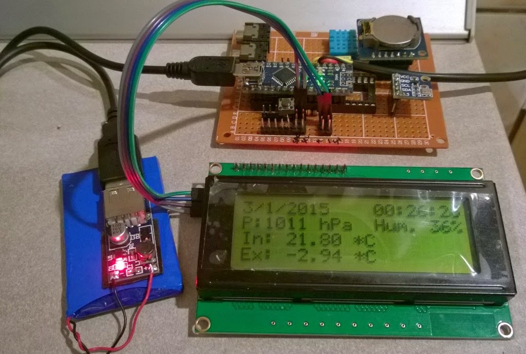
 Standul DARC dedicat Arduino.
 Standul ARR.


Radioamatorii italieni au demonstrat eficienta intr-o multime de situatii de urgenta astfel incat guvernul (lor) le-a pus la dispozitie fonduri pentru extinderea dotarii.
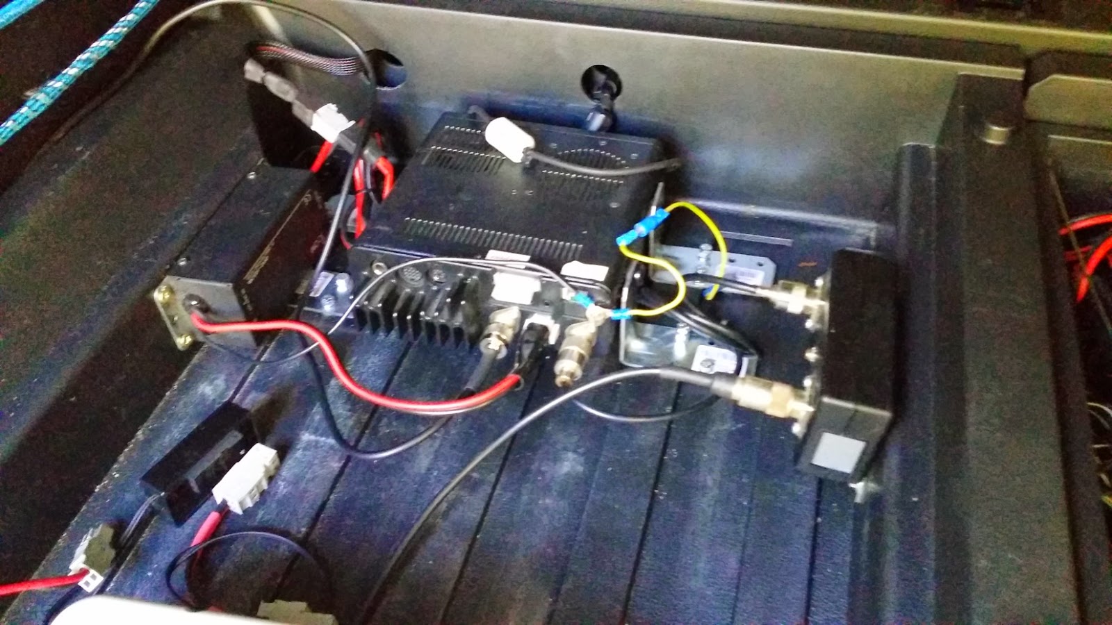
Banii au fost cheltuiti, printre altele, pe o instalatie de comunicatie via satelit geostationar COMERCIAL, echipamentul din imagine fiind nodul de interconectare cu retelele guvernamentale.


 Nu stiu la ce privea pustoaica atat de atenta dar se observa ca are controlul parental activat, in spate.


USKA.

ELEKRAFT.

Mi-am dat seama ca lipseste ceva. Sau cineva. Asa ca m-am uitat dupa standul Kenwood insa nu am reusit sa il gasesc!


Microfon remote BlueTooth pentru statia mobila Hytera.


Spre norocul meu, seminarul dedicat comunicatiilor in situatii de urgenta a inceput cu intarziere. Am ajuns la timp Foaierul Est, tocmai in capatul celalalt al complexului expozitional la timp sa prind prezentarea lui Greg Mossop, coordonatorul IARU Region I, dupa care am stat la palavre constructive inca vreo ora! TNX Greg!


 Ce am mai vazut interesant? O rulota cu un mic pilon capabil sa sustina un Inverted V si o antena VHF/UHF. Tocmai bun pentru "rapid deployment" in situatii de urgenta si o replica a masinii de criptat "Enigma", tocmai buna de criptat mesajele in situatii de urgenta! HI, glumeam!


 In paralel cu Ham Fair a avut loc si Makers Fair, adica, in traducere libera, "Targul constructorilor". O multime de tineri care isi demonstrau si exersau indemanarea fie pe costume, pe montaje electronice, pe modificari de carcase de calculatoare fie pe software pentru imprimante 3D!


 Am mai dat o tura rapida prin hale ...


... dupa care am plecat!

 Iata si cateva imagini de prin orasel. Scuze pentru calitate, sunt facute cu telefonul.


 Anul acesta am stat in Lindau, un minunat orasel pe o micuta insula, ceva mai la Est de FS.


 Cam atat deocamdata.
Daca mai imi aduc aminte, pun la comentarii.
73 de Adrian YO3HJV

D1DNR-Pirate radio from pirate country

$
0
0
Today I catch on 20m band a strange callsign: D1DNR.
Searching a little on the internet I found that the operator is from so-called Donetsk Republic.
This is a teritory controlled by separatist armed groups. Basically, it's a region under control of a terrorist group (as defined by the administration of Ukraine).
Donetsk is recognised only by South Osetia, another terrorist/separatist region.
As a authorised ham operator, I remember that I cannot make QSO (radio contacts) with non-authorised stations!
And D1DNR falls into this category as the Donetsk "administration" is not recognised by ITU and IARU! Period!
For me, the callsign D1DNR is just another way for "Mother Russia" to seek legitimacy for it's terrorist activities using the radioamateurs.
So, every QSO with D1DNR and other "Donetsk Republic" stations is clearly a helping hand to separatists.
If you listen to the QSO's, you will find that many russian stations are happy to talk with this pirate station from the pirate Donetsk!

A little extras from Wikipedia about Donetsk Republic:

The entity was declared on 7 April 2014 by a group of armed and masked militants led by Russian Col. Igor Girkin[18] who at the time occupied the Regional Administration and the City Hall buildings in Donetsk.[19][20][21][22][23] Occupation of government buildings then spread to other cities in the region.

Strange Frequency Hopping

$
0
0
I reached my second location, outside the noise of the city.
Here, my SDR works beautifull and revealed me a whole new world of signals!
I saw a strange frequency hopping signal. On both, vertical and horizontal antennas the signal is strong suggesting it came from CIS because the signals from West Europe are stronger on the horizontal antenna than the vertical at this hour.

So, here are the pictures:


Does anyone have ideea about what is this?

Viewing all 210 articles
Browse latest View live


Latest Images